
Dielectric Elastomer Actuator Fabrication and Modelling
Fabrication of Dielectric Elastomer Actuators for use as Soft Material Stiffness Sensors
Project Period : August 2023 - Present
Project Overview : Modelled, Designed and Fabricated a Dielectric Elastomer Actuator (DEA) aka artificial muscle for use as soft material stiffness sensor. This project was under Dr Alex Chortos as a part of the Bionic Interfaces Prototyping Lab. The project is still in progress and this page details the work done as of December 2023.
Contributors : Pranav Parigi, Alex Chortos
1 Abstract
Mechanical stiffness of soft materials is vital to the design and understanding of soft robotics. Development of a small-scale sensor capable of continuous monitoring will allow detailed measurements of materials continuously. The goal of this project is to utilize Dielectric Elastomer Actuators (DEA) to design a cantilever-style bending actuator to stress a material and measure its deformation. DEAs can “self-sense” which means the deformation of the actuator can be measured through variation of capacitance across it. Thus, the sensor is capable of actuating the target site and measuring deformation simultaneously. The sensor was first modelled to understand the deformation and blocking forces with different materials and thicknesses. The results of the model were used to fabricate an initial sample DEA. The development of such a sensor is novel both in its application in sensing and in the use of DEA’s self-sensing and actuation properties simultaneously. Such a sensor can easily be scaled for different applications for in-vivo and in-vitro tissue sensing for biological applications.
2 Introduction
Dielectric Elastomer Actuators (DEAs) are soft robotic actuators with a soft elastomer layer sandwiched between two electrodes. On application of a large voltage across the electrodes, the Maxwell stress causes the elastomer layer to deform and thereby cause an actuation [1]. The relative stiffness of the different layers can be manipulated to obtain different kinds of actuation types such as, in plane (Fig 1.), cantilever bending (Fig 2.), and fiber DEAs [3]. Due to their design with two parallel electrodes across a dielectric material they behave as capacitors. When the dielectric material deforms under Maxwell stress the capacitance value across the actuator changes, thereby acting as a sensor. This property is known as “self-sensing” and can be used to identify how much the actuator has deformed under different voltages and stresses. Combining the force application of a DEA with its self-sensing allows for the development of a material stiffness sensor that is small, energy dense, and biocompatible. In this report the method of designing and fabricating the DEAs are detailed. The results section details the performance of the DEAs and elastomer breakdown tests performed on the samples.

Figure 1 : In-plane Actuation of DEAs [1].

Figure 2 : Cantilever Bending DEA [2].
2. Methods
2.1 Design and Modelling of Bending DEAs
Designing a DEA for material sensing requires an actuator that can apply significant stress to deform a material while also having a large change in capacitance. The complexity of the actuator is also limited by fabrication tools and equipment available to the lab. With the restrictions in place a Cantilever bending DEA was chosen as the ideal design for this process. The structure consists of a stiff, flexible, non-stretchable electrode (Layer 1); a soft, elastic dielectric with a large breakdown field (Layer 2); and a soft, elastic electrode (Layer 3).
The stiff layer was chosen to be a 50 µm PET film with one side metallized. The PET has a very large Young’s modulus and doesn’t stretch under the applied stresses. The metal coating allows it to be used as an electrode while also adhering to the elastomer layer well.
The middle elastomer layer was chosen to be Sylgard 184 (Polydimethylsiloxane elastomer) with a 20:1 ratio by weight to the crosslinker. The elastomer has a breakdown strength of ~250 V/ µm [5] and a Young’s modulus of 200 - 1000 kPa. PDMS is a biocompatible elastomer and is regularly used in DEA fabrication.
The top soft electrode is made with 22 % Styrene-butadiene-Styrene (SBS) with carbon black dissolved in it. The material is soft and flexible with Young’s modulus ~ 1 MPa and resistance around ~ 1k Ohm. These properties make it ideal as a top layer electrode.

Figure 3 : DEA structure [4]
The variation in thicknesses between the materials is vital to the performance of the actuator. There was also a need to validate whether the proposed design would function under the voltage conditions we could supply. A model was adapted from the work of Balakrisnan, Bavani, et al. [4] to understand how the bending radius varied with voltage, material thickness, and Young’s Modulus. The following equation (Eq 1) was used to calculate the radius of curvature R. These equations were used in combination with the Maxwell Stress equation (Eq 2) for parallel plate capacitors to model the variation in radius of curvature.

Equation 1 : Radius of Curvature of DEA.

Equation 2 : Electrostatic Stress on Elastomer Layer

The key assumptions made in this model are as follows:
Linear stress strain characteristics of Elastomer layer with uniform properties in the elastic region.
Layer 2 deformation (α) is primarily due to the electrostatic forces and is uniform across length of the actuator.
Both elastomer layer (Layer 2) and soft electrode (Layer 3) deform by the same percentage.
One -dimensional bending is considered (Bending along width of actuator is ignored).
Edge effects in the actuator are ignored and layers are assumed to be perfectly adhered together.
2.1 Fabrication of DEAs
Elastomer and Stiff Electrode Layer:
PET film is cut to a size of 8x5 cm and placed in an ultrasonic cleaning machine.
5 g of Sylgard 184 and 0.25 g of cross-linker (20:1) are mixed in a centrifuge.
Elastomer is spin coated on the PET film at ~500 RPM for 90 seconds. This should create an elastomer layer of around 100 µm thickness.
The elastomer is then cured at 373 K for 5 minutes.
Region coated by elastomer must be 8x3 cm in width to allow space to connect to HV supply.
Fig 4. Below shows a sample that has been prepared as mentioned above.

Figure 4 : Elastomer Fabrication.
SBS Electrode:
A solution of “22 % SBS” (16.13% wt.), Carbon Black (3.22% wt.) and Toluene (80.65% wt.) is mixed (Weight percentage of elements given in parentheses).
The solution is left to dissolve for a day.
The solution is then blade coated onto Bytac sheet to a thickness of around 100 microns to make the electrode sheet.
The dimensions of the final cut electrode should be 8x1 cm. This ensures that no arcing takes place between the electrode and metallized PET film layer.
Fig 5. Is an image of the final electrode.

Figure 5 : SBS Electrode
Complete DEA Assembly:
The electrode is placed on the center of the elastomer layer as shown in Fig 6 and 7.
Care must be taken to isolate the positive and negative terminals to prevent arcing in the system.
DC voltage from 1kV to 10 kV is supplied to the DEA to actuate the sample.
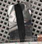
Figure 6 : Assembled DEA.

Figure 7 : Sample Wiring set up for DEA.
3 Results
3.1 Modelling Results:
Layer 2 Thickness Variation and Voltage Variation:
Length: 5 cm
Layer Widths 0.05, 0.04, 0.01 m for Layer 1,2 and 3 respectively.
Layer 2 Young’s Modulus: 200 kPa
Layer 1 Young's Modulus: 3400 MPa
Layer 3 Young's Modulus: 1 MPa
a_1 = a_2
t_3 = 150 microns
·
Figure 8 : Plot of DEA Radius of Curvature with Voltage and Thickness
The image above shows the variation of the DEA’s radius of curvature and tip deflection with different parameters. The operating range of the intended design is highlighted by the marker. The actuator shows a significant drop in performance as the thickness of layer 2 drops with a very large bending radius at 10-micron thicknesses. This behavior is in line with the expected curve for other such actuators as reduction in thickness of the elastomer layer increases the electrostatic force and reduces the effective bending stiffness. However, as we detail in the next section, our limitations are the breakdown voltage of the elastomer which reduces drastically with thickness. Hence, we must be around the 100-micron thickness range with 2.5kV applied voltage to reliably use the actuator. Even at our thicknesses we expect to see a 27 mm tip deflection which is enough for a visible actuation.
3.2 Physical DEA testing:
The sample was connected to a high voltage power supply as shown in Fig.7 and cycled through voltages from 0 to 10kV. The initial test was to look for visible actuation in the sample. The results showed that there was no actuation in the sample for any of the voltage ranges with the dielectric breaking down before any actuation could take place. The visible actuation is the first step to developing the actuator’s force and deformation capabilities for our required application. To understand these results a breakdown test was done on the elastomer material. A small drop of gallium was placed on top of the elastomer surface and voltage was increased at an increment of 0.2 kV until a sudden jump in current was seen and we could conclude that the material broke down. A cross section of the sample was also inspected under a microscope to see if there were any impurities in the sample. Fig 9 below shows the cross section of the sample under a microscope with 10x zoom. The air bubbles and impurities highlighted in red reduce the effective breakdown strength in the region causing the elastomer to breakdown at voltages much lower than expected. This result was further validated with the E- gain testing in Fig. 10.

Figure 9 : Cross - section of elastomer and PET film under a microscope. The regions highlighted in red are impurities and air bubbles that reduce the breakdown strength.
The images below show graphs of applied voltage and current vs time on the sample. We can see that the current (Orange) remains close to zero till 2kV applied voltage. Above this, the elastomer layer breaks down and there is a spike in the current drawn. For PDMS that is 130 µm thick we expect a breakdown voltage of close to 32kV (250 V/ µm breakdown strength of PDMS), thus we are getting 1/16th the expected performance. This test clearly shows the effects of the impurities in the elastomer layer. Repeating the test with another sample at another location shows similar results as shown in Fig. 11.

Figure 10 : E-Gain Breakdown Testing for Sample 1. Breakdown at around 2kV.

Figure 11 : E-Gain Breakdown Testing for Sample 2. Breakdown at around 2.5kV.
4 Conclusions and Future Work
The work done throughout this semester has focused on the design and fabrication of DEAs for the purpose of developing a material stiffness sensor. There were significant challenges in fabricating samples reliably and deviation in properties from the expected values. The testing done on breakdown voltages shows that the operating voltage range of the DEAs is significantly lower than expected and hence the design must be changed to accommodate the same. The model is a very helpful tool to quantitatively understand how certain design changes will affect the performance of the actuator. Using the results and learnings from this work, significant improvements can be made to the design to achieve the desired results.
The next steps for this project include using the knowledge from this semester to redesign the actuator to work in a more suitable voltage range accounting for the real breakdown voltage of the elastomer and not just the theoretical value. More long term, after developing an actuator, would be the characterization of the force, strain, and the self-sensing properties. These can then be combined into a PID controller to develop the sensor as needed.
5 References
[1] Jung, Kwangmok, et al. “A Self-Sensing Dielectric Elastomer Actuator.” Sensors and Actuators. A. Physical., vol. 143, no. 2, 2008, pp. 343–51, https://doi.org/10.1016/j.sna.2007.10.076.
[2] Böse, Holger, et al. “Modeling of the Actuation Performance of Dielectric Elastomer Unimorph Bending Actuators Consisting of Different Materials.” Proceedings of SPIE - The International Society for Optical Engineering, vol. 12482, SPIE, 2023, pp. 124820L-124820L – 19, https://doi.org/10.1117/12.2658490.
[3] Zhao, Huichan, et al. “Compact Dielectric Elastomer Linear Actuators.” Advanced Functional Materials, vol. 28, no. 42, 2018, https://doi.org/10.1002/adfm.201804328.
[4] Balakrisnan, Bavani, et al. “Design of Bending Multi-Layer Electroactive Polymer Actuators.” Smart Materials and Structures, vol. 24, no. 4, 2015, pp. 45032–14, https://doi.org/10.1088/0964-1726/24/4/045032.
[5] Gerratt, Aaron P., and Sarah Bergbreiter. “Dielectric Breakdown of PDMS Thin Films.” Journal of Micromechanics and Microengineering, vol. 23, no. 6, 2013, pp. 67001–07, https://doi.org/10.1088/0960-1317/23/6/067001.
[6] DeVoe, D. L., and A. P. Pisano. “Modeling and Optimal Design of Piezoelectric Cantilever Microactuators.” Journal of Microelectromechanical Systems, vol. 6, no. 3, 1997, pp. 266–70, https://doi.org/10.1109/84.623116.